Selecting an industrial valve requires knowing its flow capability. Learn about the valve flow coefficient, its calculation method, and why it matters in making the correct valve selection.

Image Source: XHVAL
Valve Cv
What it is
The valve Cv demonstrates how much fluid or substance can pass through the valve under its extreme open conditions. Formally known as the valve flow coefficient, it is defined as the gallons per minute water volume that goes through the open valve at 1 pound-fore per square inch (PSI). Determining this coefficient is essential when selecting control valves.
Examples of valve Cv explained
To understand this technical concept better, you can refer to the example problem below.
Let’s say that you are using your industrial valve to control water flow, which has a specific gravity of 1. If its valve Cv is 1.00, this means that:
- It will allow 1 gallon per minute to pass through.
- It is under the pressure of 1 PSI.
Under the same specific gravity and pressure, the valve Cv should be 2.00 if you want it to have a flow rate of 2 gallons per minute. Overall, it shows that the valve Cv allows you to control your pipelines more precisely.
Valve Cv Formula

While you can find valve Cv calculators online, understanding its core formula is a better way to have a good grasp of the concept. The formula above consists of the following:
- Cv = valve flow coefficient
- Q = rate of flow
- SG = specific gravity
- ΔP = pressure drop
Note that you cannot use the valve flow coefficient formula if any of these components are undetermined.
Flashing & Cavitation, Valve Pressure Drop vs Flow Rate: Differences Among These Cv Factors
Viscosity correction factor
The standard valve Cv values on the market have water as the base fluid, but the valves can also be used in processing many other substances with varying viscosities. Fortunately, most manufacturing projects involve fluids whose viscosity differences can be ignored. If you require specific valves related to viscous conditions, you may refer to the correction factors below.
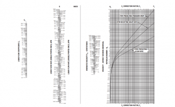
Image Source: Emerson
Rate of flow
The rate of flow is pretty intuitive with its name. Often represented in gallons per minute (GPM), this variable shows the amount of fluid going through the valve’s opening per set time. You can find it using the fluid volume and how long it takes for it to bypass the valve.
For example, you are processing two gallons of water. It took it 5 seconds to go through the valve. Hence, the rate of flow in GPM is 24.
Pressure drop
The pressure drop in PSI refers to the difference in pressure along a pipe due to the fluid’s friction against the tube. It is the hardest component to determine since it also considers the length of the pipe, the density of the fluid, diameter, and more. Referring to available charts from resource platforms like The Engineering Toolbox would be more straightforward.
How to Calculate Valve Flow Coefficient
Step 1: Determine the necessary numbers
To be able to use the valve flow coefficient formula, you must first find the numbers that you will substitute for the given variables. Determine the rate of flow, pressure drop, and specific gravity.
Example:
- Rate of flow (Q): 5 GPM
- Pressure drop (ΔP): 2 PSI
- Specific gravity: 1
Step 2: Replace the variables in the formula
Recall that the valve flow coefficient formula is Cv = Q * √(SG / ΔP). Plugging the numbers into the variables, we get: Cv = 5 * √(1 / 2).
Step 3: Calculate
This step involves basic arithmetic rules like PEMDAS. Below is a basic flow of the equation solution.
| Cv = 5 * √(1 / 2) | |
|---|---|
| Cv = 5 * √(0.5) | Solve the parenthesis. |
| Cv = 5 * 0.70710678118 | Find the square root of the result in line 2. |
| Cv = 3.53553390593 ≈ 3.54 | Multiply by the flow rate 5. Round off. |
While the solution is straightforward with a clear set of rules according to the given formula, the first step of determining the correct numbers you need may pose some difficulty.
Cv Flow
Cv to GPM

While it’s more common for professionals to determine the valve flow coefficient for their pipes, converting the Cv to GPM may also be important to get the correct flow rate anticipated. Note that to find the GPM, you need these three values: Cv, ΔP, and SG.
Cv to Kv

Another concept related to the valve flow coefficient is the flow factor. The flow coefficient is an Imperial unit, while the flow factor is its equivalent in the metric system. There are two ways to convert between the two:
- From Cv to Kv = 0.865 * Cv
- From Kv to Cv = 1.156 * Kv
Cv to SCFM
| CV TO SCFM CONVERSION FACTOR | |||||||
|---|---|---|---|---|---|---|---|
| PSI | 40 | 50 | 60 | 70 | 80 | 90 | 100 |
| Factor | 0.0370 | 0.0312 | 0.0270 | 0.0238 | 0.0212 | 0.0192 | 0.0177 |
Table from Cole-Parmer®

The standard cubic feet per minute value represents the flow capacity at precise air pressures, making it different from Cv, which applies to all pressures. Although uncommon, converting Cv to SCFM lets you know about more accurate calculations of a valve’s flow capacity. To get SCFM, simply divide the Cv by a factor that corresponds to specific air pressures in PSI.
Cv Practice Problem
Here’s another example of determining the correct valve flow coefficient that you need for your project.
| Given | Q = 2 GPM SG = 1 ΔP = 5 PSI |
|---|---|
| Formula | Cv = Q * √(SG / ΔP) |
| Solution | Cv = 2 * √(1 / 5) Cv = 2 * √(0.2) Cv = 2 * 0.4472135955 Cv = 0.894427191 ≈ 0.89 |
Valve Cv Circulations
Control valve Cv circulation with chart
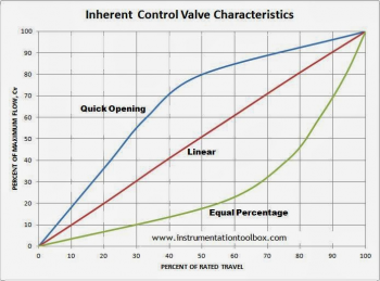
Image Source: Learning Instrumentation And Control Engineering
While the valve flow coefficient is calculated at the fully opened state of a valve, it can also be configured to more specific valve travels (or valve openings). The table above shows the relationship between the Cv and the opening percentage of the control valve.
Ball valve Cv circulation with chart

Image Source: Valmatic
This table demonstrates the rate of valve opening according to the rotation of the shaft. It also represents the control precision differences between ball valves and globe valves.
Globe valve Cv circulation with chart

Image Source: Applied Flow Technology
Controlling the flow rate involves the valve’s opening level and its equivalent valve Cv. This chart presents the characteristic curves of various types of valves like globe valves, ball valves, and more, which may give insight into the precision of control depending on the valve type.
Check valve Cv circulation with chart
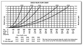
Image Source: Hansen Products (NZ) Limited
Notice that the table above details the GPM, Kv value, Cv value, and pressure drop of the check valve in several parts. These are all data that were determined using the given formulas we’ve discussed.
Butterfly valve Cv circulation with chart

Image Source: Kimray
This table demonstrates the difference between a 2” and 3” butterfly valve. As displayed, the maximum Cv’s reached under their fully open states are 47 and 117, respectively.
Gate valve Cv circulation with chart

Image Source: Industrial Controls
This table shows the various trends between the maximum flow and valve travel of different valve types.
Needle valve Cv circulation with chart

Image Source: Advance Electric Co., Inc.
For this table, the flow rate is evaluated against the number of turns at various values of pressure drops.
Conclusion
To grasp the most suitable valve size for your pipes, considering the valve flow coefficient or valve Cv is essential. This allows you to achieve the appropriate flow capacity that you want for your projects, and it can even provide you with finer control over your flow rate. If you are looking for quality industrial valves, visit XHVAL today.