
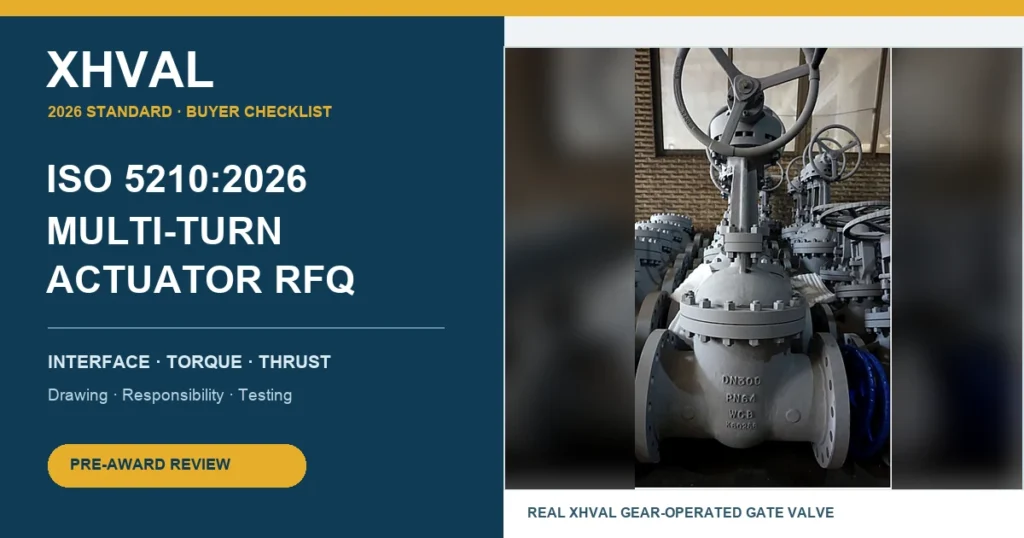
An RFQ can correctly specify a gate or globe valve and still leave a critical gap: who is responsible for making the valve, gearbox, actuator, drive components and mounting interface work as one assembly?
ISO published ISO 5210:2026, Industrial valves — Multi-turn actuator attachments, Edition 4, in February 2026. Its public abstract covers attachment-flange dimensions, driving-component dimensions, and reference torque and thrust values. For buyers, the practical message is simple: naming an interface standard does not replace the application data, sizing calculation, drawings and assembly responsibility needed for a reliable package.
Quick buyer verdict
Do not approve a motor-operated gate or globe valve quotation that states only an actuator model and “ISO 5210 compliant.” Before commercial comparison, require the supplier to show the mechanical interface, valve load basis, actuator output basis, limits of responsibility, and final assembly documents.
| RFQ field | Minimum information to request | Why it matters |
|---|---|---|
| Valve duty | Isolation, throttling, emergency duty, frequency and required travel | Duty changes sizing and endurance expectations |
| Service data | Size, class/PN, fluid, pressure, differential pressure, temperature and flow direction | Valve load depends on the actual service |
| Interface | ISO 5210 flange designation, drive form, dimensions and orientation | A standard name alone does not prove the parts match |
| Valve loads | Required operating torque and thrust through travel, plus maximum allowable limits | Prevents under-sizing and component overload |
| Actuator output | Output torque/thrust at minimum supply and worst credible condition | Catalogue maximums may not represent site conditions |
| Intermediate parts | Gearbox, stem nut, adaptor, bracket, coupling or extension details | These components transmit the full load |
| Controls | Power supply, fail action, cycle time, limit/torque switches and local controls | Defines how the package behaves in the plant |
| Documents | GA, interface drawing, sizing sheet, wiring, IOM and test records | Allows approval before shipment |
What ISO 5210:2026 does — and does not do
The ISO public listing says the 2026 edition specifies requirements for attaching multi-turn actuators to industrial valves or intermediate supports. It also covers driving-component dimensions and reference torque and thrust values for the specified flanges.
That interface framework is valuable, but it does not determine the complete actuator size for a specific valve and service. Buyers still need the manufacturer’s load data and an agreed design margin. A mechanically compatible flange can still be paired with an actuator that is too weak, too powerful, too fast, or unsuitable for the environment.
Eight checks before approving the actuator package
1. State the exact valve and service case
Give the valve type, size, pressure class, materials, end connection, design pressure and temperature, maximum differential pressure, fluid condition, required shutoff direction, operating frequency and installation orientation.
2. Separate torque from thrust
Multi-turn rising-stem valves can impose both rotary torque and axial thrust on the drive system. Ask for the required values and their direction through opening and closing. Do not accept a single unexplained “operating torque” figure when thrust is also relevant.
3. Request maximum allowable limits
The package needs enough output to operate the valve at the worst credible condition without exceeding stem, stem nut, yoke, gearbox or valve limits. Ask for both the required operating load and the maximum allowable load.
4. Define the interface on a drawing
The approval drawing should identify the flange designation, bolt pattern, pilot or spigot, drive form, stem/stem-nut dimensions, orientation and any intermediate support. Written compliance without dimensions leaves too much room for site mismatch.
5. Size at the minimum available supply
For an electric actuator, define voltage, frequency and allowable voltage variation. For pneumatic or hydraulic arrangements, define the minimum available pressure. State whether cold starts, emergency operation, low ambient temperature or other abnormal conditions must be included.
6. Control operating speed
Opening and closing time affects process behaviour, surge risk, motor duty and gearbox loading. State the required travel time and allowable tolerance rather than accepting the supplier’s default speed.
7. Assign single-package responsibility
If the valve, gearbox and actuator come from different suppliers, identify who owns sizing, interface verification, assembly, functional testing and warranty. The safest RFQ assigns one party responsibility for the complete operated-valve package.
8. List the approval and final documents
Request the valve datasheet, actuator datasheet, sizing calculation, interface drawing, GA drawing, wiring diagram, control schematic, material/coating details, test procedure, certificates, IOM manual and deviation list as applicable.
Gate valve and globe valve application notes
For a gate valve, ask how seating/unseating load, packing friction, differential pressure, stem condition and installation orientation are reflected in the sizing basis.
For a globe valve, define whether the duty is isolation or throttling and confirm flow direction, differential pressure and any project-specific trim requirements. A multi-turn actuator interface standard does not turn an isolation globe valve into a control-valve package.
Butterfly and ball valves are normally part-turn applications; their attachment and actuation questions are different. For butterfly-valve selection and project support, see XHVAL Butterfly Valve.
Copy-ready RFQ clause
Supplier shall provide a complete operated-valve package suitable for the stated service and duty. The quotation shall identify the applicable edition of ISO 5210 and the governing valve design and test standards. Supplier shall submit valve operating torque and thrust data, maximum allowable limits, actuator/gearbox sizing calculations at the minimum available supply condition, selected design margins, interface and GA drawings, intermediate-component details, opening/closing time, control accessories, functional-test procedure, IOM documents and a complete deviation list. Mechanical interface compliance alone shall not be accepted as evidence of actuator sizing.
Final pre-award checklist
- Exact standard editions are stated.
- The worst operating case and supply condition are defined.
- Required torque and thrust are separated and traceable.
- Maximum allowable valve and drive-train loads are provided.
- The ISO 5210 interface appears on an approval drawing.
- Gearbox and intermediate components are included in the load review.
- Speed, controls, switches and local operation are defined.
- One supplier owns complete-package compatibility and testing.
- Documents, certificates and deviations are listed before award.