What Is the Ball Valve Mechanism?
A ball valve mechanism uses a rotating ball with a bore through it. A stem connects the ball to a handle or actuator. When the bore aligns with the pipe, flow passes through; when the ball turns 90 degrees, the solid side blocks the flow path. Seats and seals support the closing interface. Standard ball valves are mainly used for shutoff, not precise throttling.
How the Ball Valve Mechanism Works in 3 Steps
The basic ball valve mechanism is a quarter-turn motion system. The operator does not move a gate up and down or push a plug linearly. Instead, the handle or actuator rotates a stem, and the stem rotates the ball inside the valve body.
Step 1: The handle or actuator turns the stem
The handle, lever, or actuator is the external control point. When it turns, it transfers rotational movement into the valve through the stem.
In a manual valve, this usually means an operator turns a handle. In an actuated valve, the movement may come from an electric, pneumatic, or hydraulic actuator. This article treats actuation only as a general operating method, not as a claim about any specific supplier’s automation capability.
Step 2: The stem rotates the bored ball
The stem connects to the ball. As the stem turns, the ball turns with it. The ball has a hole through the center, usually called the bore or port.
This is the key part of the mechanism. The ball itself is not just a solid plug. It is a rotating closure element with a flow passage through it.
Step 3: The bore aligns with or blocks the flow path
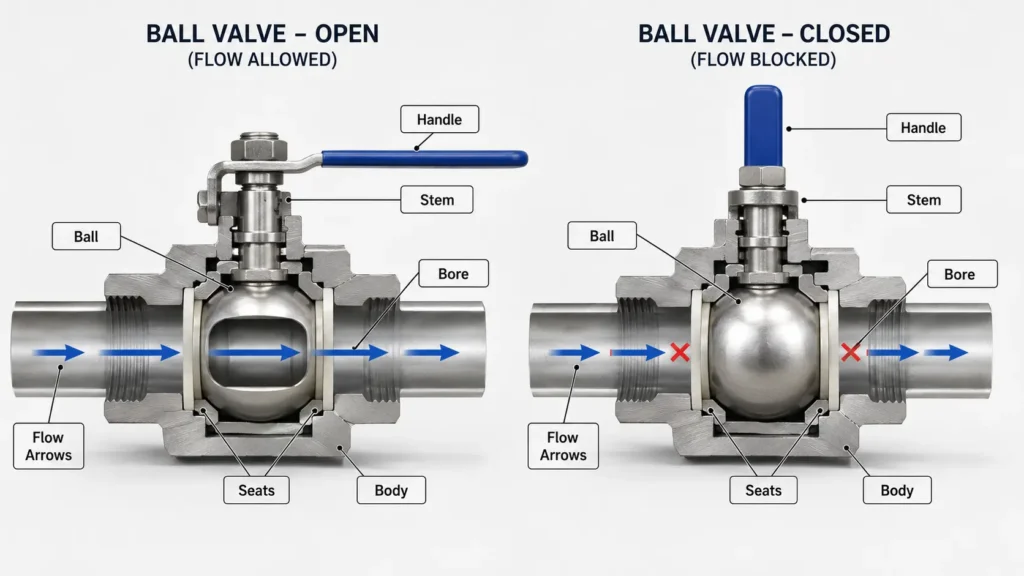
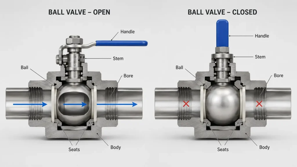
When the bore points in the same direction as the pipe, the valve is open. Flow can pass through the bore.
When the ball rotates a quarter turn, the bore becomes perpendicular to the pipe. The flow path is blocked by the solid side of the ball. This is why many ball valves can move from open to closed with a 90-degree handle movement.
What Parts Control the Ball Valve Mechanism?
A ball valve mechanism depends on several parts working together. The table below keeps the explanation practical: what each part does, and what an engineer or buyer may need to check before selection.
| Part | Mechanism role | What to check |
|---|---|---|
| Ball | Rotates inside the valve body to open or block the flow path. | Confirm whether the design is floating, trunnion-supported, or another specified design. |
| Bore / port | The hole through the ball that creates the flow path when aligned with the pipe. | Confirm full-port, reduced-port, or V-port / characterized design if flow behavior matters. |
| Stem | Transfers movement from the handle or actuator to the ball. | Check whether manual operation or actuation is needed. |
| Seats | Support the ball and form the sealing interface between the ball and body. | Confirm seat material and service conditions with the supplier or engineering team. |
| Seals / packing | Help manage sealing around the stem and body interfaces. | Do not assume compatibility without checking media, temperature, and service conditions. |
| Valve body | Holds the internal parts and connects to the pipeline. | Confirm body style, connection type, and maintenance access requirements. |
| Handle / actuator | Provides the external force that rotates the stem and ball. | Confirm access, operating frequency, and whether remote or automated operation is needed. |
Open, Closed, and Partially Open Positions
The ball valve mechanism is easiest to understand by looking at three positions: open, closed, and partially open. The open and closed positions are straightforward. The partially open position needs more caution because a standard ball valve is usually not the best choice for precise flow regulation.
| Position | Bore direction | Flow effect | Caution |
|---|---|---|---|
| Open | Bore aligned with pipe. | Flow can pass through the valve. | Confirm bore / port design if pressure drop or flow restriction matters. |
| Closed | Bore perpendicular to pipe. | The solid side of the ball blocks the flow path. | Do not describe closure as “zero leakage” unless a specific tested product claim is verified. |
| Partially open | Bore partly aligned with pipe. | Flow may pass through a reduced opening. | Standard ball valves are generally better treated as on/off valves, not precision throttling valves. |
A standard ball valve can be left partially open in some situations, but that does not make it a precision control valve. For buyers, the practical question is not only “can the handle stop halfway?” The better question is: “Does the application need simple shutoff, or does it need controlled flow behavior?”
If controlled flow is required, a characterized or V-port design may need review rather than a standard on/off ball valve.
How Mechanism Details Affect Selection
The same basic mechanism can be configured in different ways. These differences matter because they affect restriction, support, operating method, and selection questions.
| Mechanism factor | Why it matters | Buyer or engineer check |
|---|---|---|
| Full-port vs reduced-port bore | The bore size affects how restricted the flow path is. | Confirm whether pressure drop, cleaning, or pigging requirements make bore size important. |
| Floating vs trunnion ball support | Ball support changes how the ball is held and how loads are managed. | Confirm whether the valve design is appropriate for the line size, pressure class, and service conditions. |
| Standard port vs V-port / characterized design | Standard ball valves are mainly shutoff devices; shaped ports may support more controlled flow behavior. | Ask whether the application needs on/off isolation or flow regulation. |
| Manual handle vs actuator | The operating method affects access, remote operation, and integration. | Confirm operating frequency, access, control signal, and actuator requirements. |
| Seat / seal configuration | Seats and seals affect the closing interface. | Confirm media, temperature, pressure, and material compatibility with qualified technical support. |
Full-port vs reduced-port bore
The bore through the ball may be close to the pipe diameter or smaller than the pipe diameter. Full-port designs create a less restricted flow path than reduced-port designs. When flow restriction, pressure drop, cleaning access, or pigging matters, confirm whether the valve should be full-port or reduced-port before selection.
For an RFQ, do not simply ask for “a ball valve” if bore size matters. State whether full-port or reduced-port is required, or ask for technical review if you are unsure.
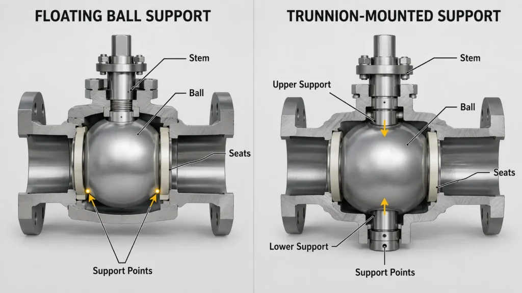
Floating vs trunnion ball support
Floating and trunnion-mounted ball valves differ mainly in how the ball is supported.
In a floating design, the ball is not held by a trunnion and can move slightly against the seat. In a trunnion-mounted design, the ball has additional mechanical support.
This article does not claim that one design is always better. The right design depends on the service conditions, size, pressure class, maintenance expectations, and supplier engineering review.
Manual handle vs actuator
The external operating method also matters. A manual handle is simple and visible. An actuator may be needed when the valve must be operated remotely, integrated into a control system, or cycled under conditions where manual operation is not practical.
This article does not make actuator sizing or automation suitability claims. Those require system details such as torque requirement, operating frequency, available power or air supply, control method, and operating environment.
Mechanism Limits and Common Problems
A ball valve mechanism is simple, but it is not risk-free. Many problems start when the valve is used outside the conditions it was selected for, or when the system contains media that affects the ball, seats, seals, or bore.
Common mechanism-related issues can include:
- debris trapped around the ball or seats;
- seat or seal wear;
- abrasive particles affecting the ball or sealing surface;
- obstruction that prevents full closure;
- sticking after long periods in one position;
- poor performance when a standard on/off ball valve is used as a throttling valve.
Debris, seat or seal damage, abrasive wear, obstruction, sticking, and throttling misuse should be treated as general risk examples. Exact diagnosis depends on the actual system, media, pressure, temperature, and valve design.
For technical review, describe the actual media, operating pressure, operating temperature, solids content, actuation method, and service cycle. A valve drawing or previous valve specification can also help the review process.
Buyer/RFQ Checklist: What to Confirm Before Selection Support
A clear RFQ reduces back-and-forth and helps the supplier or engineering team understand whether a standard ball valve mechanism fits the application.
Use this checklist before requesting selection support:
- Media: liquid, gas, steam, slurry, chemical, or other service media
- Pressure and temperature: normal operating range and any peak conditions
- Flow function: simple on/off shutoff, diverting, mixing, or flow regulation
- Port/bore requirement: full-port, reduced-port, V-port, or unknown
- Valve design: floating, trunnion, multi-port, or to be recommended
- Connection type: threaded, flanged, welded, clamp, or other connection
- Material preference: body, ball, stem, seats, and seals if already specified
- Actuation: manual handle, electric actuator, pneumatic actuator, hydraulic actuator, or unknown
- Operating access: manual access, remote location, safety clearance, or control-system integration needs
- Quantity and project stage: sample, replacement, prototype, production, or maintenance order
- Documents needed: drawing, datasheet, inspection documents, certificates, or other documents if required
Do not assume that every supplier can provide every document or meet every condition. If compliance, safety, material compatibility, pressure rating, temperature rating, or testing is important, ask what evidence is available and have the requirement reviewed before purchase.
FAQ: Ball Valve Mechanism
What is the mechanism of a ball valve?
A ball valve mechanism uses a rotating ball with a bore through the center. The stem turns the ball. When the bore aligns with the pipe, the valve is open; when the ball turns 90 degrees and the bore is perpendicular to the flow path, the valve is closed.
How does a ball valve open and close?
A handle or actuator turns the stem, and the stem rotates the bored ball inside the valve body. In the open position, the bore lines up with the pipe. In the closed position, the bore turns away from the flow path and the solid side of the ball blocks the passage.
What parts control the ball valve mechanism?
The main mechanism parts are the ball, bore, stem, seats, seals or packing, valve body, and handle or actuator. The ball and bore control the flow path. The stem transfers rotation. The seats and seals support the closing interface. The body holds the parts and connects to the pipeline.
Can a ball valve be partially open?
A ball valve can be physically positioned partially open, but a standard ball valve is usually better used as an on/off valve. If the application needs controlled flow regulation, ask whether a characterized or V-port design is required.
Can a ball valve control flow?
A standard ball valve can restrict flow when partially open, but that is not the same as precise flow control. For applications that need regulated flow behavior, a V-port or characterized ball valve may need review.
How do floating and trunnion ball valve mechanisms differ?
Floating and trunnion ball valves differ in ball support. In a floating design, the ball is not held by a trunnion and can move slightly against the seat. In a trunnion design, the ball has additional mechanical support. The right design depends on service conditions and engineering review.
What are common ball valve mechanism problems?
Common mechanism-related problems can include debris, seat or seal damage, abrasive wear, obstruction, sticking, or poor results from using a standard ball valve for throttling. Exact diagnosis depends on the system, media, pressure, temperature, and valve design.
What should buyers check before selecting a ball valve mechanism?
Buyers should check media, pressure, temperature, flow-control need, port or bore type, connection type, material requirements, actuation method, quantity, and document requirements. If pressure, temperature, compatibility, compliance, or safety matters, ask for technical review and supporting documentation before purchase.
Need Help Reviewing a Ball Valve Mechanism?
Before requesting selection support, prepare the media, pressure and temperature conditions, port or bore requirement, connection type, material preference, actuation need, quantity, and any required drawings or documents.
A clear request helps the technical team review whether the valve should be a standard shutoff ball valve, a full-port or reduced-port design, a floating or trunnion design, or a characterized / V-port option for flow-control needs. Final suitability should be confirmed against the actual service conditions.